1875: Proposal for a Tunnel Under the Channel
In 1875 a book "Nouveau Projet de Tunnel Transmarin pour la Traversée
de la Manche" was published in Paris. The author was J. Castanier.
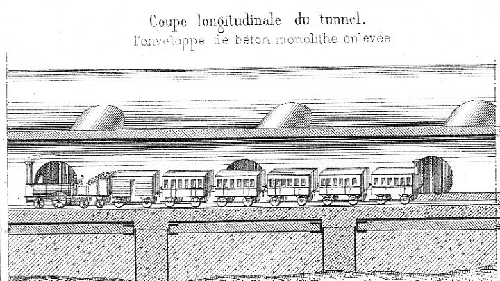
The proposal was for a double-track tunnel consisting of two separate tubes.
The picture below shows one of the tubes. There is an elevated compartment
for the guard on the last coach!

The parallell tubes where to be connected by transversal tubes at intervals.
Several such connections are shown above. One reason for the connections
was to increase the strenght of the unnel structure. .
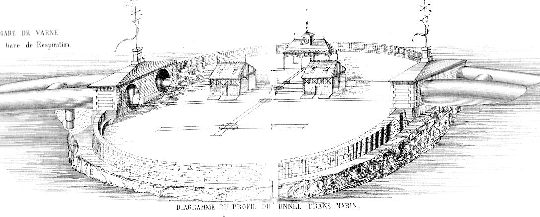
Smoke emission from the engines might become a problem. Castanier proposed
to this end that the tunnel should emerge briefly on an artificial island
built on the banks of Varne. At these banks the depth of the channel was
only five metres. The picture below shows most of the tunnel; it is remarked
that the drawing is not to scale. Dover is to the left, Calais
to the right.

Below is a detail picture of the artificial island with the "breathing station"
(Gare de respiration). The diameter of the island was to be 150 - 200
metres. It should be provided with lighthouses and a staff building.
The turntables where probably for temporary storage of defect rolling stock,
and perhaps cars for provisions to the staff of the island station.

All pictures scanned from a copy of Castaniers book found in the library
of Svenska Järnvägsklubbens (the Swedish Railway Club) .
1917: Signalling for an Electrified Channel Tunnel
Railway Gazette (UK) for November 23, 1917, had a description of signalling
and safety measures for a tunnel between England and France. The summary
below is from an abstract of this article in "Railway Signal Engineer" (USA)
for February 1918 [pp 59-60]:
General Data
- Total length of the double-track tunnel was to be 30 miles.
- Maximum speed 40 miles per hour for passenger trains, 25 mph for freight
- The line was to be electrified
- No conveyance of dangerous goods to be allowed
- All freight wagons to have continous brakes and oil axle-boxes
Block Working and Safety Arrangements in Tunnel
- Only one train in each direction to be allowed to use the tunnel simultaneously.
- Trainstops to apply brakes if signal passed at danger
- Signal boxes at the tunnel entrances to be equipped with "electrically-operated
diagram frames" to indicate exakt position of trains (tunnel to have
continous track-circuiting?)
- Semaphores at tunnel entrances to be electrically locked in danger
position if track through tunnel + overlap occupied.
- An illuminated distance marker and a telephone to be provided at each
quarter-mile
- Tell-tale wires through tunnel to set off alarm bells in signal boxes
if cut
Home
Last updated November 18, 2006


