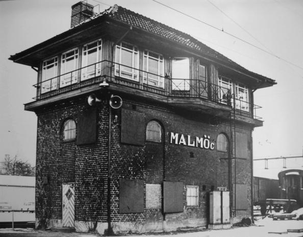
Westinghouse Style K Powerframe in Malmö, Sweden
The Westinghouse Brake & Signal Co. Ltd. Style 'K' power frame at
Malmö Central was the only Westinghouse frame in Sweden, but it was
important as it pioneered the switch from german-style to british-influenced
signalling principles in Sweden. Only by taking this step was it possible
to control large stations from a single signal-box. It was also an incentive
to the swedish Signalbolaget (a subsidiary of the Ericsson telecom
company) to develop an electrically-locked frame.
Until 1925 Malmö Central Station was controlled from several mechanical
signalboxes. The station was rebuilt during the 1920s, and the State
Railways wanted to rationalise the signalling and control the whole layout
from a single box. This was only possible if shunting could take place on
signalled and locked routes. All previous interlockings in Sweden were of
german types, where trains run on locked routes, but shunting is regulated
by hand-signals. Track circuits were uncommon. At all but the smallest
stations several boxes where necessary to control the layout. These boxes
were under the control of a local controller (train director) using electrical
releases for the signal levers.
In british-style interlockings it is customary for shunting operations
to be directed by fixed signals on locked routes, so the State Railways
decided to buy a Style K frame from the british Westinghouse Brake &
Saxby Signal Co. The Swedish Signalbolaget (signalling subsidiary
of the Ericsson telecom company) acted as an intermediary.
The powerbox was brought into use in 1925. The picture shows the box in
1965 [Göteborgs Landsarkiv]
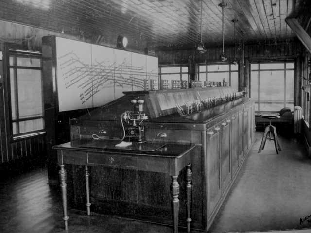
The picture above, from 1925 - 1933, shows the frame and the illuminated
diagram. [Swedish Railway Museum, picture number 6081].
The signal levers were of the push-pull-type. The lever could control two
routes, as the signalman could either push or pull the lever from the neutral
position. The annotation for the routes accordingly used the suffix
psh for push and
pll for pull.
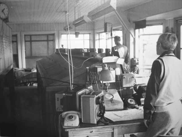
This picture, probably from the 1970s or 1980s, shows a variety of telecommunications
equipment. [Swedish Railway Museum, picture number 6082].
Technical description
This description is based on data in Banavdelningens berättelse
(State Railway infrastructure department's annual report)1925 pp 102
-
The frame was equipped with
- 33 signal levers for 14 starting signals, 5 home signals and 57 shunting
signals
- 41 levers for 63 switches and 3 derails (blocks)
A small installation compared to the style K frame
at London Bridge (311 levers)!
There were 57 track circuits. 77 main routes and 186 shunting routes could
be set up. The interlocking used 98 AC relays and 173 DC relays.
Power supply:
- Machines for switches and derails were furnished from
a storage battery in the signalbox. This battery was charged through a mercury
arc rectifier. A rotary convertor was available as a standby.
- DC relays were supplied from a 12 volt storage battery,
charged by a pendulum rectifier.
- A transformer with secondary windings for 55 and 110
volts supplied signals, track circuits and AC relays.
Signals
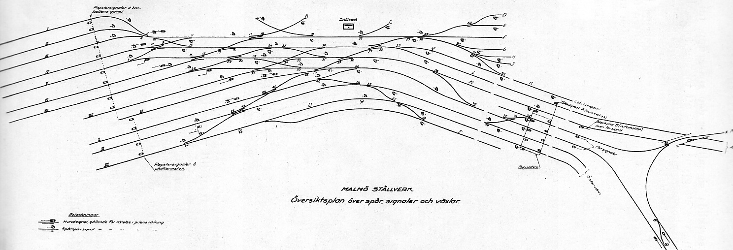
The diagram reproduced below is from Banavdelningens berättelse 1925,
page 105. The all-over roof covering the main platforms is near
the left edge. Platform tracks VIII to XII belong to the so called Local
Station, used by short-distance trains. The 'box is near the upper edge.
The double-tracked Southern Mainline to Stockholm leaves to the right.
Connecting tracks to the freight yard are brought over the mainline on a
viaduct. The two tracks disappearing near the lower right corner of
the diagram are the so called Contintental Line to Trelleborg and the track
to the State Railway's rolling stock works. Breaks in the track on
the diagram are used where the actual distance is considerably longer than
shown.
The home signals are fixed to a gantry (Signalbro) spanning most of the lines.
A single green light is shown for routes to the short tracks of the Local
Station. Routes to the longer platform tracks number I - VII are signalled
by two green lights. This was contrary to later practice.
Inner starting signals could be found near the ends of most platforms.
These signals co-acted with repeater signals on the outer edge of the all-over
roof. Outer starting signals were mounted on the same gantry as the home
signals.
Shunting routes where signalled by position-light dwarf signals.
"Blockpost A" and "Blockpost B" are automatic block signals
for the Southern Mainline. Automatic block was necessary as, due to
the distance, the signalmen could not observe the tail lights of all
trains.
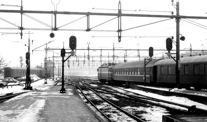
This picture, from february 1980, shows some of the inner starting signals
and a few position-light dwarf signals. The Southern Mainline was
only electrified during the 1930s, so no overhead line portals were available
for mounting the signals when the power interlocking was built.
The coach visible behind the locomotive of the departing train is a sleeper
bound for Moscow via Trelleborg - Berlin.
The Malmö interlocking used main signals as inner starting signals
(intermediate signals in current swedish terminology). This use of main signals
was standard practice in earlier mechanical and power interlockings. However,
most power interlockings built subsequently used only dwarfs as inner
starters. These dwarfs can show a green aspect to indicate that a main route
has been set up. Shunting routes are always indicated by lunar-white lights
only. Nowadays, as a safeguard against trains passing signals at danger,
dwarf signals for main routes display a red aspect at all times except when
a main route has been set up.
Levers and Indicators
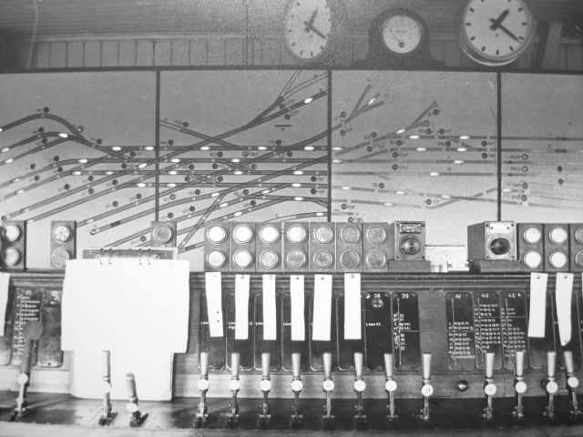
Above each lever can be seen a plate with the number of the lever
and, in the case of a signal lever, a list of other levers which are
required for the route. Signal indications are repeated on the illuminated
diagram. Free track circuits are indicated by a white light. Originally,
contrary to later practice, the track circuit lights where normally extinguished,
and lit up to indicate occupation of the track circuit. Switch position
indicators can be seen immediately above the switch levers. These indicators
were also known as windmills. Above some of the signal levers are time releases
used for instance if it is necessary to cancel a main route after the signal
has been taken off. Picture No 6086, Swedish Railway Museum.
This picture was probably shot after 1956 - the clocks on both sides of the
ammeter are non-existant on the picture taken in 1956.
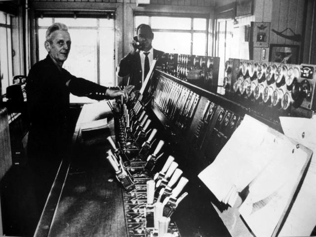
A picture from 1963 [via SJ fotoklubb, now in Göteborgs Landsarkiv]
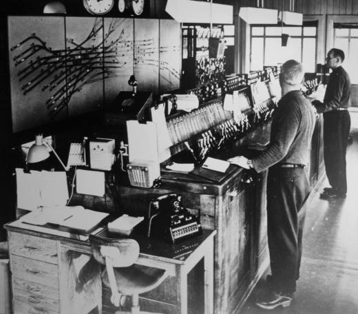
This picture is probably from 1965, and was reproduced by the Malmö
Railwaymen's Photo Club.
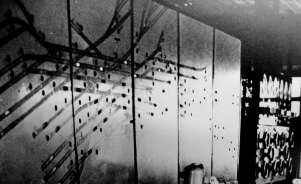
Illuminated diagram and controls and indications for the power supply.
[SJ fotoklubb Malmö, Göteborgs Landsarkiv]
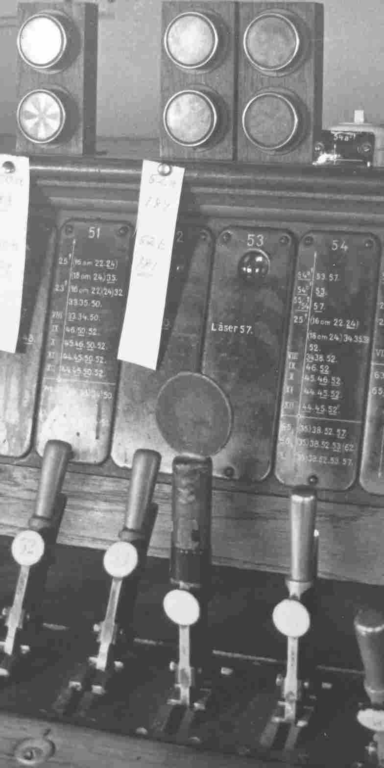
|
Left: Enlargement of part of a picture from
the swedish Railway Museum. A lever collar has been placed
on one of the levers so that it can not be thrown by the signalmen
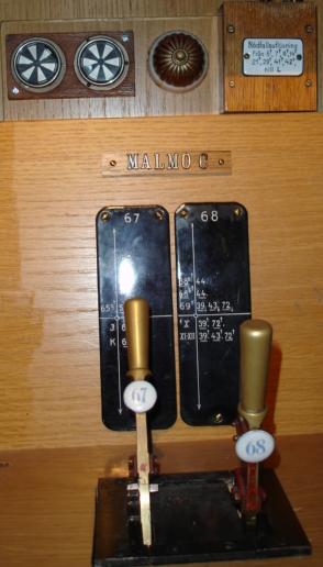
Right: A few pieces from the
frame have been preserved at the infrastructure authority's museum at Ängelholm.
The indicators are not in the same
position as on the real frame. The small box in the upper right corner is
for emergency release of a main route. This arrangement was replaced
by time releases at an unknown date [2005]
|
|
Local control. Safety and Reliability.
At interlockings built prior to the Malmö
powerbox, the work of the signalmen was controlled by a local controller
(train director, sw
tågklarerare)
using electrical releases. This was neccessary to coordinate the boxes,
and as a safety measure due to the lack of track circuits. In
the Malmö powerbox, locking and track circuits made it possible
for the signalmen to operate the interlocking plant with complete safety
without releases from the controller. The local controller's office,
near track VII, had a simplified illuminated diagram to show track occupancy
on some platform tracks, but no releases for the signals. The
local controller gave the
right away
handsignal to departing trains, but the signalmen mainly managed the
train and shunting movements on their own. This partition of work
was applied also to most later large powerframes in Sweden.
A few weeks after the interlocking had been brought into use, the
last car of an arriving train was derailed and overturned when
a switch
was thrown under the train. A guard was killed and some passengers were injured.
The cause of the accident was a faulty part in the locking frame. Otherwise,
the interlocking plant seems to have functioned well.
Relock or Replace the Powerframe?
In the middle of the 1950s, it was time again
for rebuilding Malmö Central station. The State Railways 3d district
launched the idea that the powerframe ought to be replaced by a relay
interlocking. Slackness had developed in the locking. As this was the only
British-style frame in Sweden, it was thought that maintenance could be
simplified if it was substituted by standard equipment. In a perhaps somewhat
exaggerated report, the district stated that the interlocking would have
to be taken out of use for six months if it was decided to relock and extend
the Styel K frame. During these six months hand signalling was to be used.
On the 19th September 1956 Westinghouse Brake &Signal Company
offered
- equipment for extending the interlocking due to the yard rebuilding,
£ 640
- a complete set of spare parts for the mechanical locking, £
3 525. There was also an option of renewing only parts of the locking.
Delivery would be possible 9 - 15 months after the order was placed. The
installation of the new equipment could be carried out by four locking fitters
during a 12 hours posession after preparatory work during several nights.
Alternatively, four locking fitters could accomplish the entire relocking
and extension during three weeks with disconnected locking and handsignalling.
Westinghouse mentioned that they considered the locking fitters of
the State Railways to be thoroughly conversant with the locking of the Style
K frame, and capable of carrying out the relocking and extension.
The state railways decided to relock and life-extend the powerframe. This
decision was probably influenced by a lack of suitable swedish relay interlocking
technology for large installations.
I have not as yet managed to get information on how the relocking was carried
out and how long handsignalling had to be used.
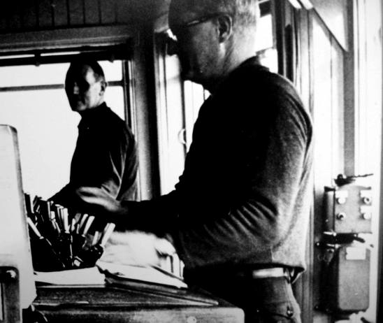
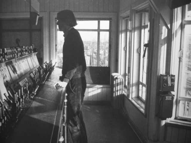 A
Above: Probably a picture
from the final decade of the box. At the window can be seen equipment
possibly used to control a switch machine which for some reason was not
on the frame
. [Swedish Railway Museum,
Picture No.6080]
Below; Picture in Göteborgs Landsarkiv, via SJ fotoklubb Malmö
The Style K frame was the most technically advanced frame with
mechanical locking in Sweden. It was also the last really big swedish
powerframe with mechanical interlocking. In 1926 or 1927 the first electrically
interlocked frame was brought into use at Hässleholm. This development
was parallell to Westinghouse's development of the Style L frame
. The Style K frame in Malmö was
replaced by a computer based interlocking in 1982
.
Sources
Documents from the State Railways in Riksarkivet (public record office)
Banavdelningens berättelse 1925
Pictures in the archive of the Swedish Railway Museum, Gävle,
and Göteborgs Landsarkiv.
Swedish Version
Home
Last updated 4 Februari 2006
